

Compressed Air & Gas Dryers
CO₂ Dryer
Beverage-grade dry CO₂ from your recovery plant, with the gas used for drying returned to your process, not vented.
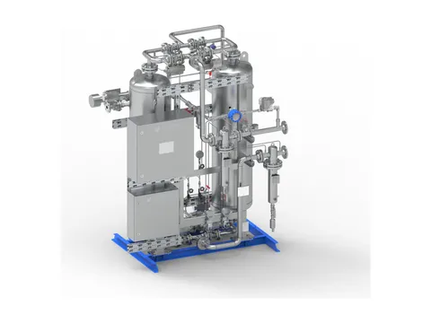
Product overview
Dry CO₂ your liquefier and your customers can rely on
Our CO₂ dryer takes the water-saturated gas in your recovery plant, typically at 15–20 bar g, and adsorbs its water on a solid desiccant until only a few ppm v/v remain. That keeps your liquefier free of ice and your product within its moisture specification.
Two towers of 3A molecular sieve share the work: one dries while the other is regenerated with heated dry CO₂, and they change roles on a cycle of several hours, so drying never stops. The regeneration gas is cooled, its water drained, and returned to your compressor suction, so the CO₂ used for regeneration is recovered rather than vented.
At 18 bar g and 25 °C, saturated CO₂ carries about 1,670 ppm v/v of water. Reaching the ISBT beverage-grade limit of 20 ppm v/v means removing about 98.8 % of it, a frost point of about −30 °C at line pressure.
- 20 ppm v/vISBT beverage-grade water limit
- 98.8 %Of the water removed, from saturation at 18 bar g and 25 °C
- About −30 °CFrost point at line pressure
- ZeroCO₂ lost in regeneration
Benefits
The problems it solves
Every recovery route leaves your CO₂ saturated with water. Here is what that water does, and how the dryer stops it.
-
Ice in the liquefier
The problem
Water reaching the condenser at liquefaction temperatures freezes as ice and CO₂ hydrate, cutting capacity until the plant stops to defrost.
How it solves it
Gas with a −30 °C frost point at line pressure cannot deposit ice at the −21 °C condensing temperature, so your refrigeration plant runs without defrost stops.
-
Failing the beverage specification
The problem
Beverage producers audit their CO₂ against the ISBT limit of 20 ppm v/v water, and gas that cannot show a compliant level cannot be supplied for carbonation.
How it solves it
Molecular sieve beds routinely deliver well below 20 ppm v/v, and continuous outlet moisture measurement gives you the records your quality audits ask for.
-
Product lost to regeneration
The problem
The CO₂ is your product, and every kilogram vented during regeneration must be recovered again or bought in.
How it solves it
The regeneration gas returns to your compressor suction. The only material leaving the loop is liquid water.
-
Carbonic acid corrosion
The problem
At 19 bar CO₂ partial pressure, condensate reaches about pH 3.3 and attacks carbon steel pipework, storage tanks and valve bodies.
How it solves it
Without liquid water, CO₂ cannot form carbonic acid, so your downstream equipment is protected and no dissolved iron reaches the product.
-
Ice in storage and distribution
The problem
Water entering the storage tank freezes as ice crystals that block level gauges, safety valves, pump suctions and vaporiser inlets.
How it solves it
Dry gas keeps your liquid CO₂ storage and distribution free of ice.
-
Product held in the bed
The problem
Many zeolites adsorb CO₂ strongly, loading the bed with product gas and competing with water for sites.
How it solves it
3A sieve pores, about 3 Å across, admit water at 2.65 Å and largely exclude CO₂ at 3.3 Å, so little product is held and the gas leaves unchanged apart from its water.
Where it’s used
Wherever CO₂ is recovered, dried and liquefied
From fermentation tanks to synthesis gas, recovered CO₂ has to be dry before it can be liquefied, stored and sold.
-
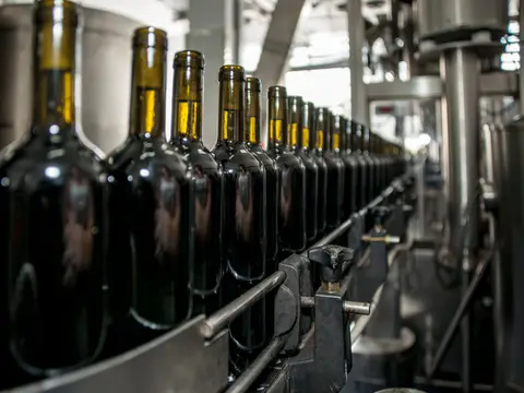
Breweries and soft drinks
Fermentation CO₂ recovered for carbonation, bottle and keg purging and tank counter-pressure, and certified to beverage grade for bottlers.
-
Ammonia and hydrogen plants
CO₂ removed from synthesis gas, purified and dried for urea production, merchant liquid CO₂ and dry ice.
-
Pharmaceuticals and extraction
CO₂ within the European Pharmacopoeia water limit of 67 ppm v/v, and recirculating CO₂ for supercritical extraction of hops, coffee and botanical oils.
Also wineries and distilleries, bioethanol plants, natural gas processing and biogas upgrading, carbon capture, utilisation and storage, industrial gas producers, food processing and dry ice, greenhouse CO₂ enrichment and water treatment.
How it works
Adsorb, heat, recover, cool
Two towers take turns. While one dries your CO₂, the other is heated to drive off its water, then cooled and made ready for its next turn.
-
1. AdsorbWet CO₂ flows down through Tower A. The 3A molecular sieve holds its water, and dry CO₂ leaves at the bottom, through the after-filter, to your liquefier.
-
2. HeatA side stream of dry CO₂ is heated and flows up through Tower B, against the drying direction, taking the sieve to typically 200–300 °C. A temperature front climbs through the bed and drives the water off.
-
3. RecoverThe hot, wet regeneration gas passes through a cooler, where most of its water condenses, and a separator drains it away. The CO₂ returns to your compressor suction, so none is vented.
-
4. CoolThe heater switches off, and unheated dry CO₂ carries the stored heat out of Tower B until it is close to process temperature. The tower returns to line pressure and waits, fully regenerated.
-
5. Change overWhen Tower A reaches the end of its adsorption phase, typically after several hours, the valves switch and the towers change roles, so drying carries on without interruption.
Typical figures for saturated CO₂ at 18 bar g and 25 °C.
Get the full details
Our brochure covers it in detail, and our questionnaire tells us what we need to recommend the right one for your plant.
Keep exploring
More from our range
Equipment for every stage of your compressed air, and our own engineers to test, commission and look after it.
-
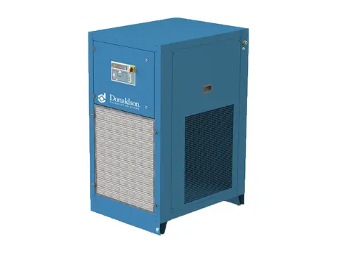
Refrigerated Air Dryers
Dry, condensate-free air for your plant, with no compressed air spent drying.
View product -
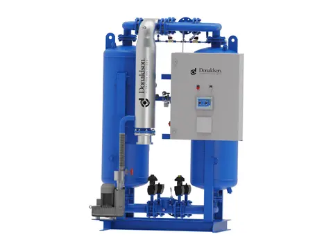
Heated Desiccant Dryers
Deep, stable dew points for your air, with heat doing the regeneration.
View product -
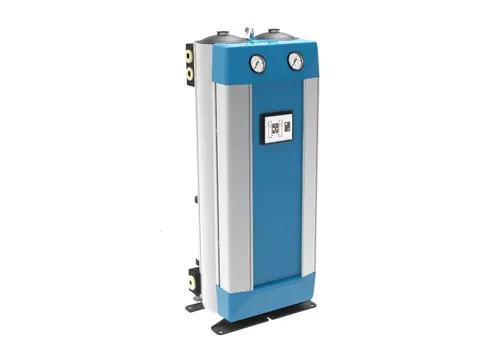
Heatless Desiccant Dryers
Deep dew points without heaters, for hazardous areas and remote sites.
View product -
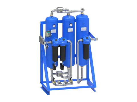
Breathing Air Systems
Your plant’s compressed air, made safe to breathe.
View product -
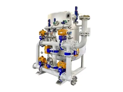
Hydrogen Dryers & De-Oxo Units
Electrolytic hydrogen purified of oxygen and water, ready for fuel cells.
View product -
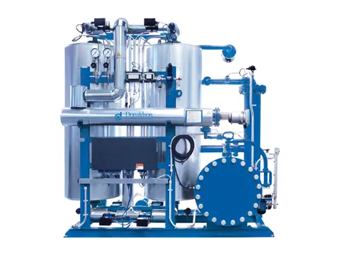
Biogas & Natural Gas Dryers
Dry, condensate-free fuel gas for your engines, boilers and upgrading plant.
View product -
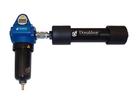
Membrane Dryers
Dry air at the point of use, with no power and no moving parts.
View product
-
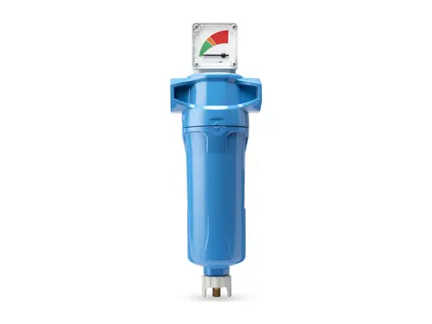
Coalescing Filters
Takes oil and water aerosols out of your air, down to 0.01 mg/m³.
View product -
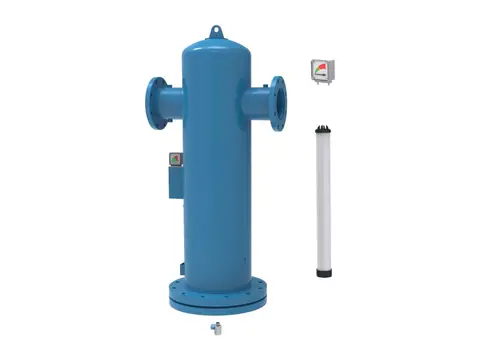
Particulate Filters
Dry, dust-free air for your plant, down to 0.01 µm particles.
View product -
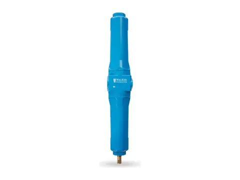
Compressed Air Duplex Filters
Change filter elements without interrupting your air supply.
View product -
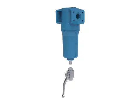
High Pressure Filters
Certified air purity for your high-pressure lines, up to 350 bar g.
View product -
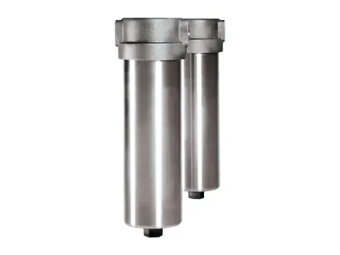
High Temperature Filters
Particle-free compressed air and gas where your process runs hot.
View product -
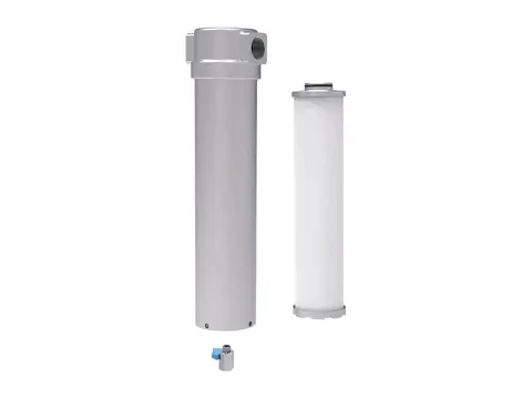
Ammonia and Refrigerant Filters
Keeps compressor oil out of your condensers and evaporators.
View product -
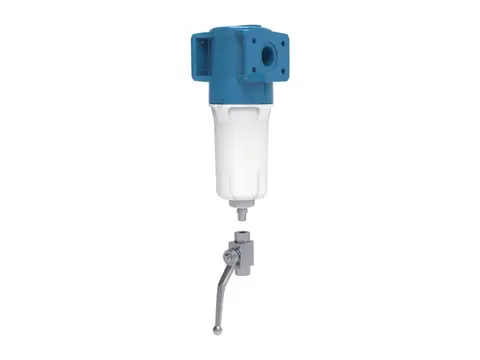
Oxygen Filters
Particle-free oxygen for your system, without adding an ignition source.
View product -
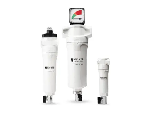
Silicone-Free Filters
Crater-free paint finishes, from air free of paint-wetting contaminants.
View product -
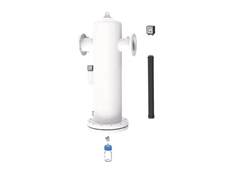
Medical Vacuum Filters
Keeps pathogens from hospital suction away from your pumps and exhaust.
View product -
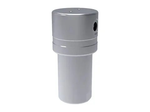
Hydrogen Filters
Particle, aerosol and oil-free hydrogen, from electrolyser to dispenser.
View product -
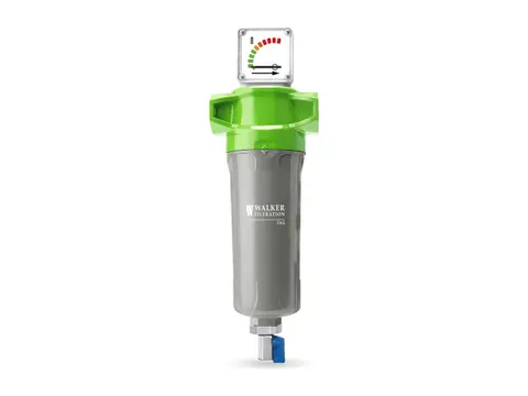
CNG Filters
Oil-free, particle-free natural gas from your compressor to the vehicle.
View product
-
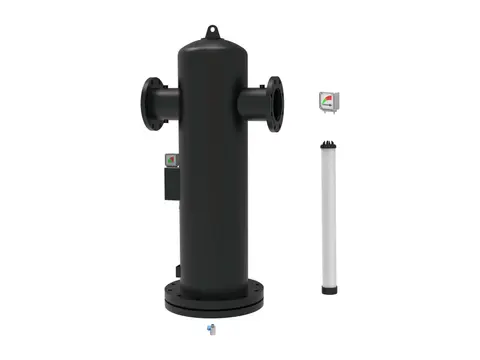
Centrifugal Moisture Separators
Bulk liquid out of your air by centrifugal force, with no element to replace.
View product -
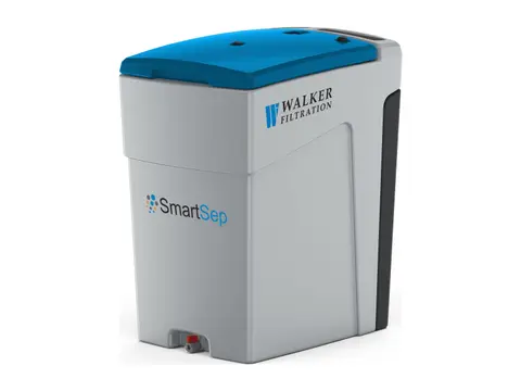
Oil Water Separator
Turns oily compressor condensate into water fit for sewer discharge.
View product -
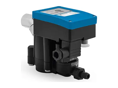
Zero-Loss Electronic Drain
Discharges every drop of condensate from your system, never your compressed air.
View product -
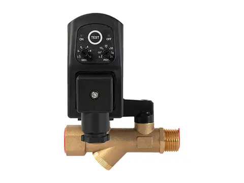
Timer Drain
Scheduled, positive condensate discharge from any collection point in your system.
View product -
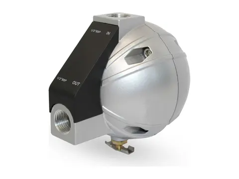
Mechanical Float Drain
Buoyancy-driven condensate removal with no power and no air loss.
View product -
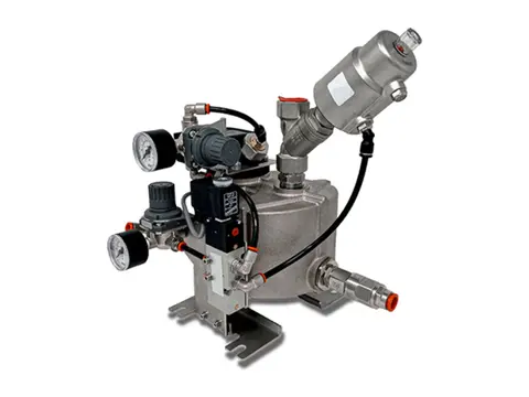
Vacuum Drain
Empties liquid from your vacuum system without breaking the vacuum.
View product
-
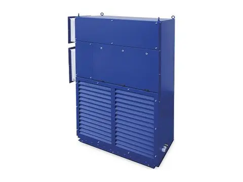
Crane Air Conditioner
Cool, clean cabins and electrical rooms for cranes working in extreme heat.
View product -
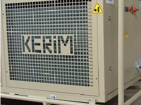
Tent Air Conditioner
Controlled climate for your tents, shelters and temporary structures.
View product -
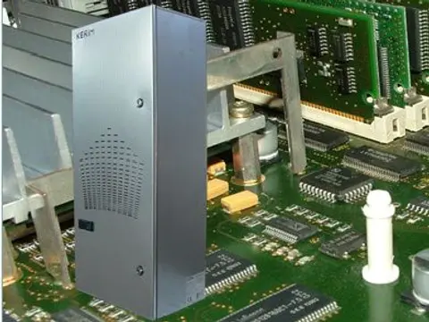
Panel Air Conditioner
Cool, clean, dry control panels, even in your hottest, dirtiest plant areas.
View product -
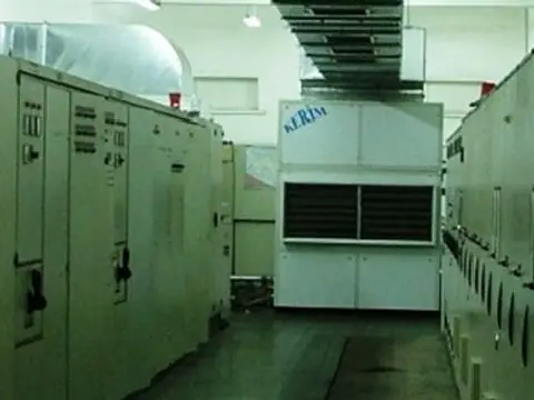
Air / Water Cooled Air Conditioner
Stable room temperatures for your electrical rooms in extreme plant heat.
View product
-
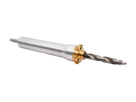
Hot Tapping
Add measurement ports to your live air lines without stopping production.
View product -
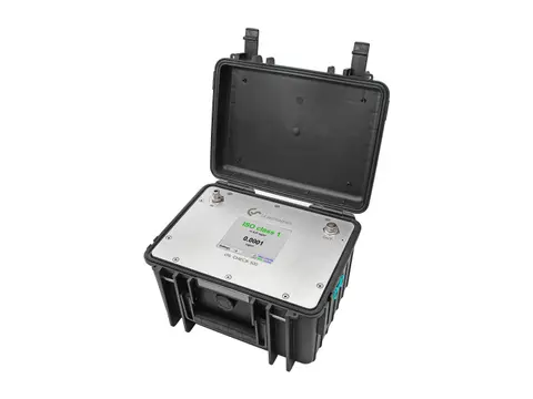
Compressed Air Quality Measurement
Prove your air's ISO 8573-1 purity: particles, oil and dew point.
View product -
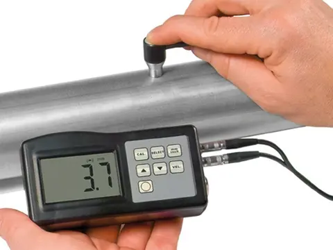
Digital Thickness Meter
Measure the metal left in your receivers and pipework, from the outside.
View product -
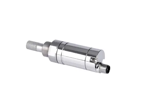
Dew Point Meter
Proof your air is dry, measured at line pressure.
View product -
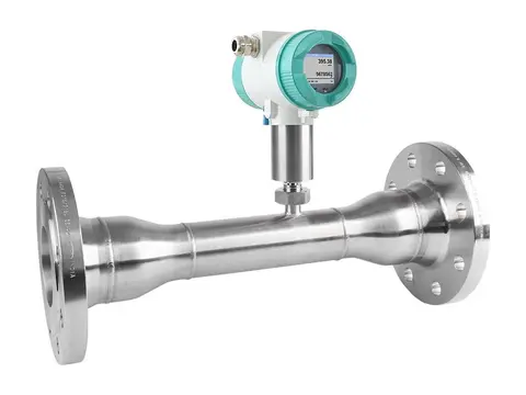
Flow Meter
True standard flow of your compressed air, whatever the line pressure.
View product -
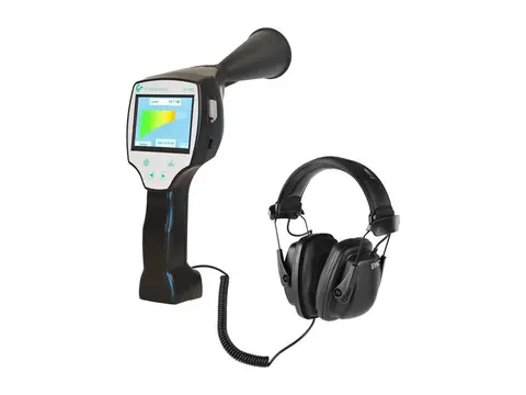
Leak Detector
Hear, locate and cost every compressed air leak in your plant.
View product -
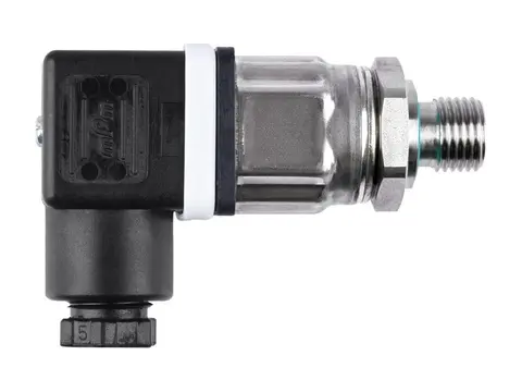
Pressure Sensor
Live pressure data from your compressor room to every point of use.
View product -
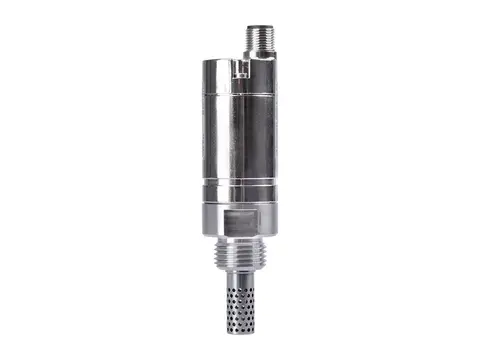
Humidity Meter
Humidity, temperature and dew point from one probe.
View product -
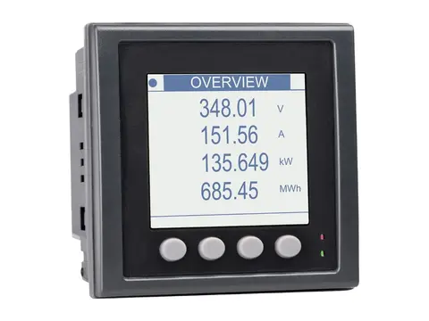
Power Meter
Measure the true power, energy and efficiency of your compressors.
View product
-
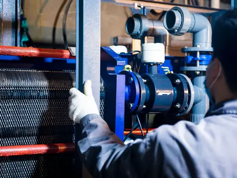
Health Testing of Compressed Air & Gas Dryers
Measured proof your dryer delivers its rated dew point.
View service -
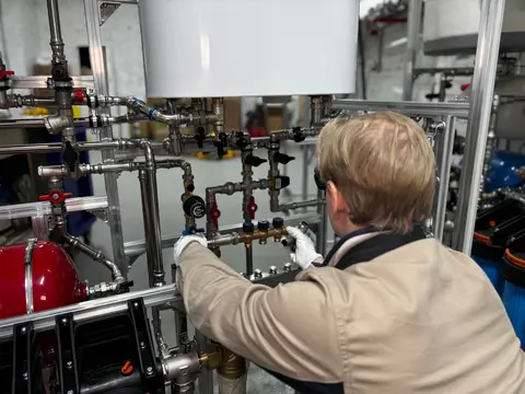
Commissioning and Service of Compressed Air & Gas Dryers
Verified dew point from first start-up through your dryer's service life.
View service -
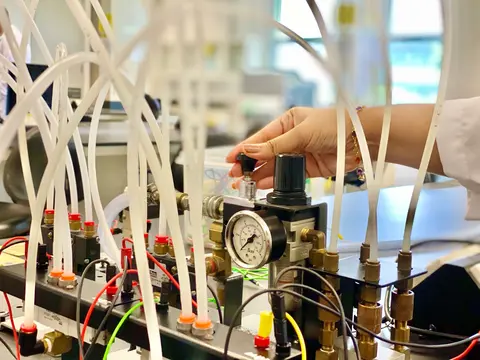
Compressed Air Quality Testing
Measured, documented proof of your compressed air purity class.
View service -
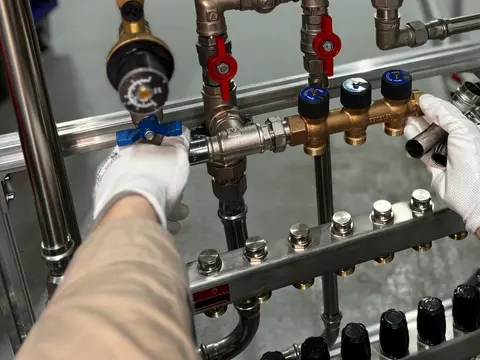
Dew Point Measurement Testing
Verified pressure dew point at the points that matter in your network.
View service -
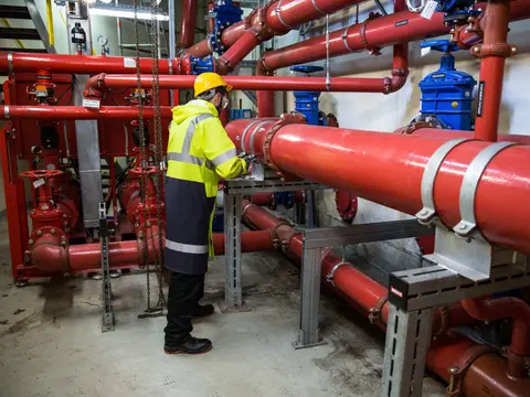
Compressed Air Flow Testing
Measured air demand, leakage and cost for your plant, not estimates.
View service -
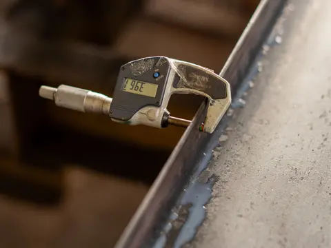
Wall Thickness Testing
Know the remaining wall, corrosion rate and safe life of your equipment.
View service -
Sourcing
Spares, consumables and whole systems for your plant, sourced globally.
View service
