
Measurement Equipments
Flow Meter
Know exactly how much air your plant uses, and how much it loses, in true standard cubic metres, whatever your line pressure.

Product overview
See where every cubic metre of your air goes
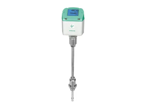
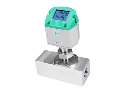
Our thermal mass flow meter measures the flow of your compressed air or technical gas by the heat the moving gas carries away from a heated sensor. That heat depends on the mass of gas passing, so the meter reads mass flow directly and reports it as standard volume flow, in m³/h, m³/min or l/s, with no separate pressure or temperature measurement.
The sensor sits inside your pipe, usually at the centreline, and the meter turns that point reading into flow through the whole pipe from its bore and the shape of the velocity profile. It totalises your consumption, and with your compressors’ electrical energy gives the specific energy of your air in kWh per standard m³.
Thermal sensors respond to low gas velocities, so one meter records both full production demand and the small flow left when every consumer is switched off: the leakage rate of your network.
- Mass flowRead directly, no pressure or temperature inputs
- ISO 1217Or DIN 1343 reference conditions
- No moving partsNothing in the flow to wear or jam
- Under pressureProbes fit through a ball valve
Benefits
Measured air, managed cost
Compressed air is one of the most expensive utilities in your plant, and most networks were installed without a flow meter. Here is what that hides, and what measurement shows.
-
Leaks you can cost
The problem
Leaks are spread over hundreds of fittings, hoses and valves, many can’t be heard over production, and energy guidance cites 20–30 % of compressor output lost in poorly maintained systems.
How it solves it
Read your main header with production stopped and the flow you see is your leakage rate, ready to cost, target and check again after repair.
-
Steady readings as pressure swings
The problem
Air at 7 bar g takes about one-eighth of its free air volume, and every change in pressure or temperature changes that ratio.
How it solves it
The meter responds to mass, so its reading stays in standard units at any line pressure and gas temperature within its rating.
-
Compressors sized to real demand
The problem
Nameplate totals overstate demand, because machines rarely all run at full consumption at the same time.
How it solves it
A flow profile shows your true peak, base load and the storage needed to cover short peaks, before you add or replace a compressor.
-
Fair cost allocation
The problem
A single compressor energy bill hides which area actually drives demand.
How it solves it
Branch meters charge each department, product line or tenant for its own consumption.
-
Evidence for ISO 50001
The problem
ISO 50001 energy management and ISO 11011:2013 assessments rest on measured demand, not estimates.
How it solves it
Totalised consumption and flow profiles, logged alongside compressor power, give your specific energy in kWh per standard m³.
-
Faults flagged early
The problem
A burst hose, a stuck drain or a blow-off valve left open wastes air unseen.
How it solves it
Alarm thresholds flag flow that rises above the expected level for the time of day.
Where it’s used
Wherever air is a cost worth knowing
From a single machine supply to the main header leaving your compressor room, flow data turns air into a figure you can manage.
-

Automotive and engineering
Branch metering allocates air cost to paint shops, body shops, machining and assembly lines.
-

Food and beverage
Bottle blowing, pneumatic conveying and packaging lines, where air is a major utility cost.
-

Pharmaceuticals
Measured consumption of tablet coating, fluid-bed and filling equipment supports validation and utility records.
-

Textiles
Air-jet looms draw large, continuous flows, and per-loom or per-shed metering tracks their consumption.
-
Glass, cement and steel
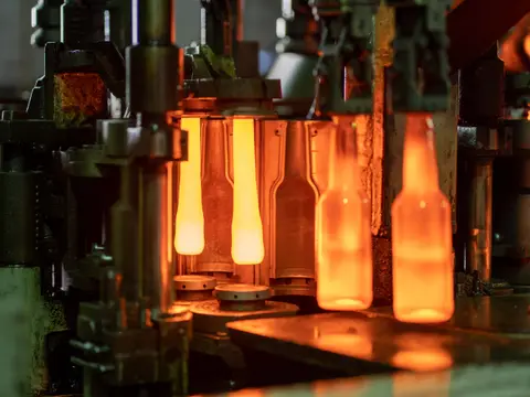
Headers supplying burners, conveying and instrument air, metered for cost allocation and demand planning.
-

Industrial gases
Gas-specific calibrations measure carbon dioxide, argon, oxygen and nitrogen supplied to welding, beverage carbonation and process users.
Also energy audits and leak surveys, clean dry air and nitrogen in electronics, nitrogen generator outlets, compressed air billed as a utility service, and commissioning checks on compressor delivery and dryer purge consumption.
How it works
Heat carried away, read as mass
A heated sensor loses heat to the air flowing past it. The more mass flows, the more power it takes to keep the sensor warm, and that power is the measurement.
-
1. Place the probeThe probe goes in through a ball valve to the pipe centreline, aligned with the flow, on a straight run of at least 15 pipe diameters upstream and 5 downstream, so the velocity profile is fully developed.
-
2. Sense the gas temperatureAn unheated platinum reference element takes on the temperature of the gas flowing past it.
-
3. Hold the heated elementA control loop holds a second platinum element a fixed amount above the gas temperature. More gas flowing past carries more heat away, and the loop raises the heating current until the difference is restored. The power it needs is the measurement.
-
4. Convert to standard flowThe calibration curve turns heating power into mass flux, and the meter applies the profile factor and your pipe’s actual bore. At 8 m/s in a 53.1 mm bore at 7 bar g and 20 °C it reads 511 m³/h, and if the pressure falls to 6 bar g with the same mass flowing, it still reads 511 m³/h.
-
5. TotaliseThe meter adds the flow up over time, in the same reference conditions as the reading. At 511 m³/h, one 24-hour day adds 12,264 m³ to the totaliser.
Example figures for air at 8 m/s in a pipe with a 53.1 mm bore, at 7 bar g and 20 °C, referred to ISO 1217 conditions.
Get the full details
Our brochure covers it in detail, and our questionnaire tells us what we need to recommend the right one for your plant.
Keep exploring
More from our range
Equipment for every stage of your compressed air, and our own engineers to test, commission and look after it.
-
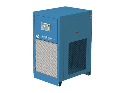
Refrigerated Air Dryers
Dry, condensate-free air for your plant, with no compressed air spent drying.
View product -
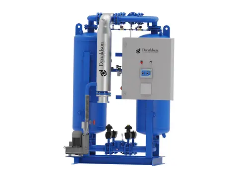
Heated Desiccant Dryers
Deep, stable dew points for your air, with heat doing the regeneration.
View product -
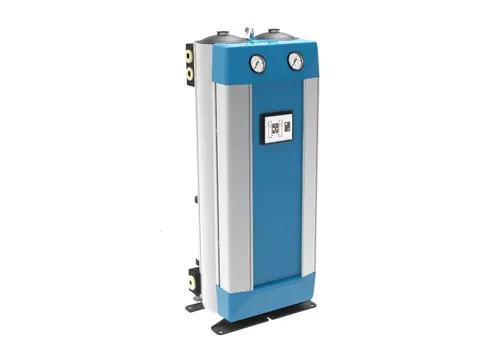
Heatless Desiccant Dryers
Deep dew points without heaters, for hazardous areas and remote sites.
View product -
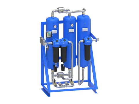
Breathing Air Systems
Your plant’s compressed air, made safe to breathe.
View product -
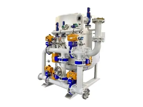
Hydrogen Dryers & De-Oxo Units
Electrolytic hydrogen purified of oxygen and water, ready for fuel cells.
View product -
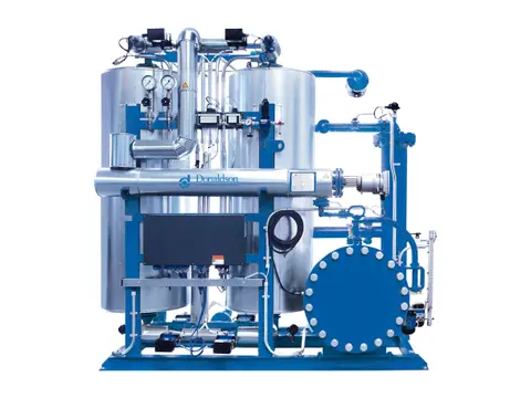
Biogas & Natural Gas Dryers
Dry, condensate-free fuel gas for your engines, boilers and upgrading plant.
View product -
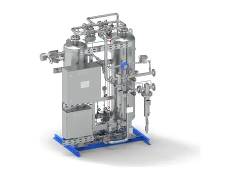
CO₂ Dryers
Beverage-grade dry CO₂ for your recovery plant, with no gas vented.
View product -
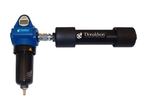
Membrane Dryers
Dry air at the point of use, with no power and no moving parts.
View product
-
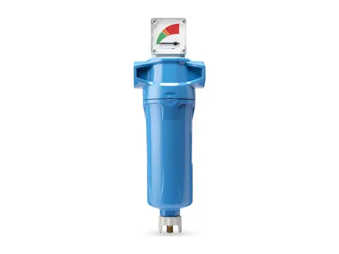
Coalescing Filters
Takes oil and water aerosols out of your air, down to 0.01 mg/m³.
View product -
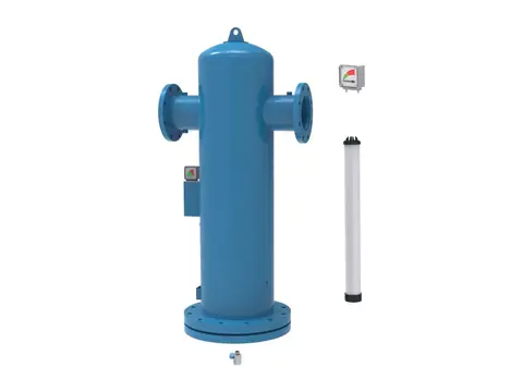
Particulate Filters
Dry, dust-free air for your plant, down to 0.01 µm particles.
View product -
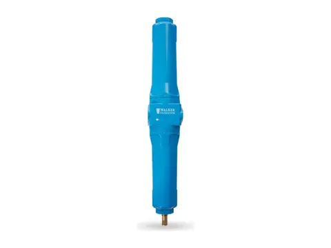
Compressed Air Duplex Filters
Change filter elements without interrupting your air supply.
View product -
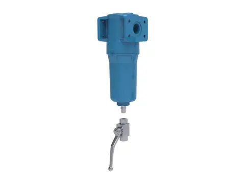
High Pressure Filters
Certified air purity for your high-pressure lines, up to 350 bar g.
View product -
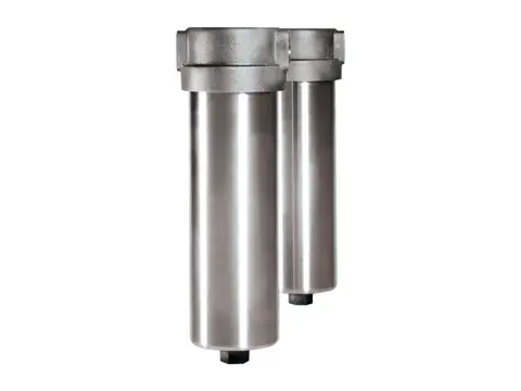
High Temperature Filters
Particle-free compressed air and gas where your process runs hot.
View product -
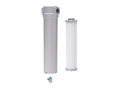
Ammonia and Refrigerant Filters
Keeps compressor oil out of your condensers and evaporators.
View product -
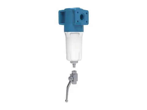
Oxygen Filters
Particle-free oxygen for your system, without adding an ignition source.
View product -
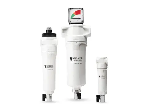
Silicone-Free Filters
Crater-free paint finishes, from air free of paint-wetting contaminants.
View product -
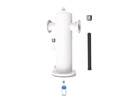
Medical Vacuum Filters
Keeps pathogens from hospital suction away from your pumps and exhaust.
View product -
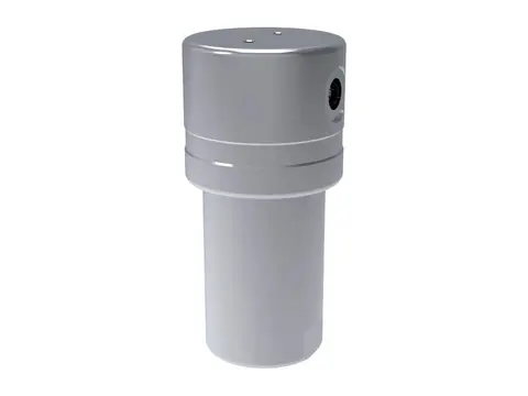
Hydrogen Filters
Particle, aerosol and oil-free hydrogen, from electrolyser to dispenser.
View product -
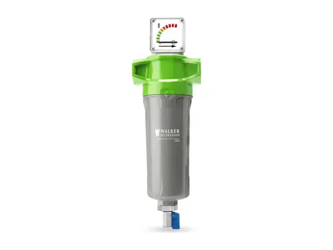
CNG Filters
Oil-free, particle-free natural gas from your compressor to the vehicle.
View product
-
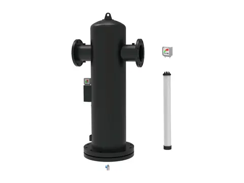
Centrifugal Moisture Separators
Bulk liquid out of your air by centrifugal force, with no element to replace.
View product -
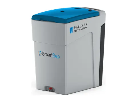
Oil Water Separator
Turns oily compressor condensate into water fit for sewer discharge.
View product -
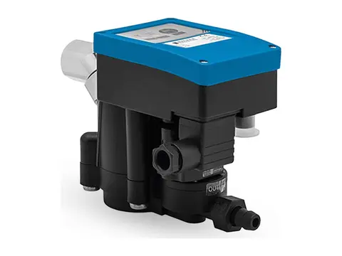
Zero-Loss Electronic Drain
Discharges every drop of condensate from your system, never your compressed air.
View product -
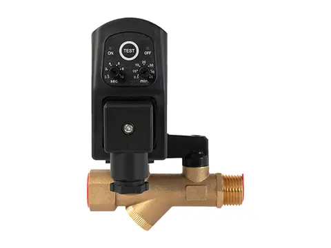
Timer Drain
Scheduled, positive condensate discharge from any collection point in your system.
View product -
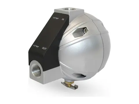
Mechanical Float Drain
Buoyancy-driven condensate removal with no power and no air loss.
View product -
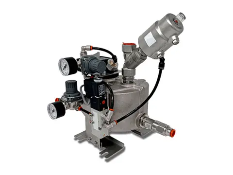
Vacuum Drain
Empties liquid from your vacuum system without breaking the vacuum.
View product
-
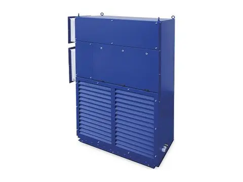
Crane Air Conditioner
Cool, clean cabins and electrical rooms for cranes working in extreme heat.
View product -
Tent Air Conditioner
Controlled climate for your tents, shelters and temporary structures.
View product -
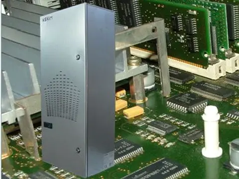
Panel Air Conditioner
Cool, clean, dry control panels, even in your hottest, dirtiest plant areas.
View product -
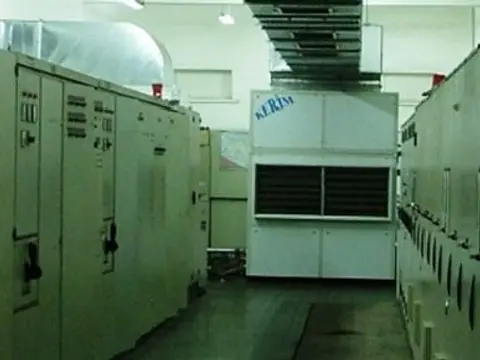
Air / Water Cooled Air Conditioner
Stable room temperatures for your electrical rooms in extreme plant heat.
View product
-
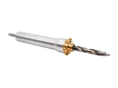
Hot Tapping
Add measurement ports to your live air lines without stopping production.
View product -
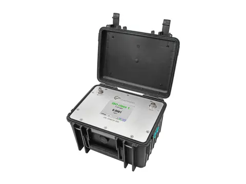
Compressed Air Quality Measurement
Prove your air's ISO 8573-1 purity: particles, oil and dew point.
View product -
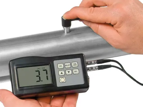
Digital Thickness Meter
Measure the metal left in your receivers and pipework, from the outside.
View product -
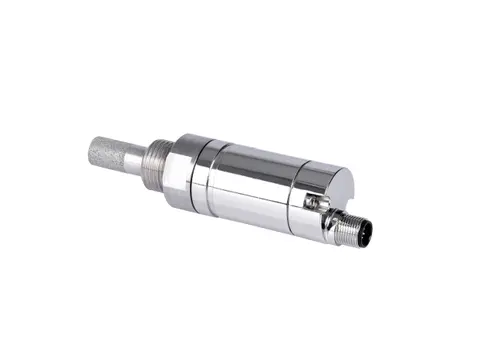
Dew Point Meter
Proof your air is dry, measured at line pressure.
View product -
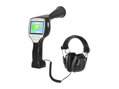
Leak Detector
Hear, locate and cost every compressed air leak in your plant.
View product -
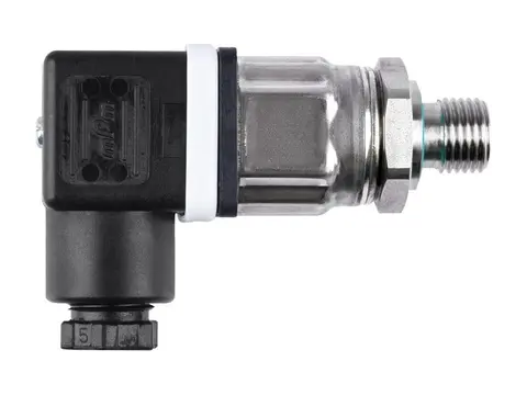
Pressure Sensor
Live pressure data from your compressor room to every point of use.
View product -
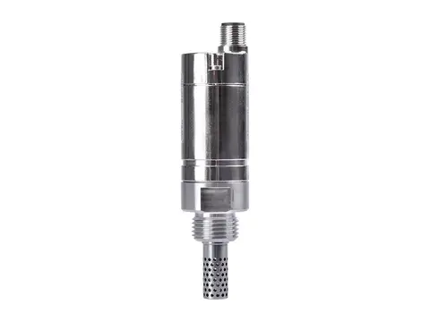
Humidity Meter
Humidity, temperature and dew point from one probe.
View product -
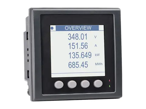
Power Meter
Measure the true power, energy and efficiency of your compressors.
View product
-
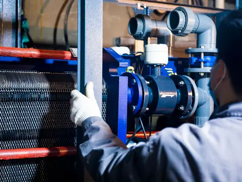
Health Testing of Compressed Air & Gas Dryers
Measured proof your dryer delivers its rated dew point.
View service -
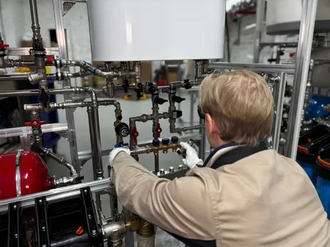
Commissioning and Service of Compressed Air & Gas Dryers
Verified dew point from first start-up through your dryer's service life.
View service -

Compressed Air Quality Testing
Measured, documented proof of your compressed air purity class.
View service -
Dew Point Measurement Testing
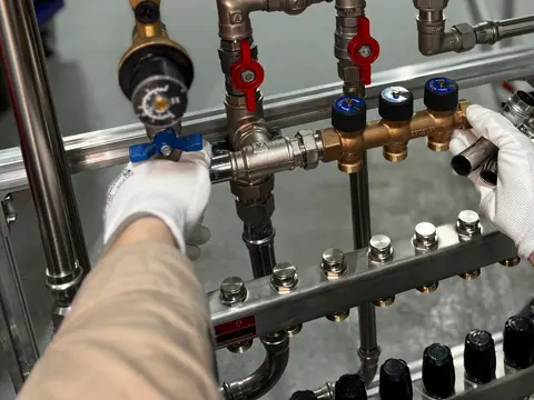
Verified pressure dew point at the points that matter in your network.
View service -
Compressed Air Flow Testing
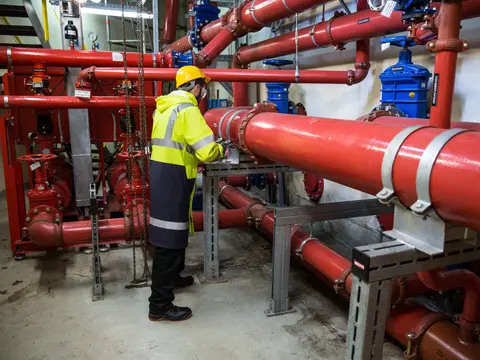
Measured air demand, leakage and cost for your plant, not estimates.
View service -
Wall Thickness Testing
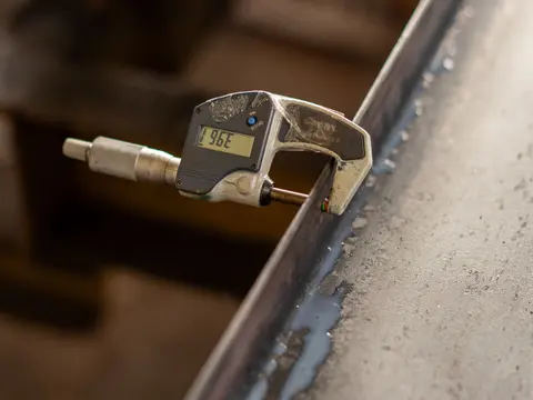
Know the remaining wall, corrosion rate and safe life of your equipment.
View service -
Sourcing
Spares, consumables and whole systems for your plant, sourced globally.
View service
